Yet Another Simple Interferometer (YASI)
YASI is a simple
20MHz radio interferometer. It uses two antennas, spaced along an
East-West baseline and two simple kit receivers, modified so that both
receivers share a common Local Oscillator (LO). A Linux computer uses a
stereo sound card to sample the audio output of both receivers. A
computer program then makes measurements of the amount of power
detected from each receiver and also measures the cross correlation of
the two receivers - essentially a measure of how similar the two
signals are.
If the radio source is in some positions with respect to the baseline,
the cross correlation will be positive, at other positions the cross
correlation will be zero or negative. If the radio source is an
astronomical object then Earth rotation will move the object through
the interferometers beam of highs and low, giving a quasi-sinusoidal
interference fringe pattern in the interferometer output. Technically
speaking, YASI is a cross correlating meridian transit radio
interferometer.
Steve Heaton is assembling our ideas into a great website here.
YASI Specs:
Frequency: 19.6-20.9 MHz, manual varactor diode tuning.
Bandwidth: 5kHz (10kHz double sideband)
Antennas: Each receiver has two half-wave dipoles phased together.
Feedline: Each 67m of RG58CU MILSPEC RG58, 8.33m Quad shielded RG6 for
dipole droplines
Baseline: 45m East-West (3 wavelengths)
Location: "Mick's Place". Simple at the ATCA site is 26.0km away on
bearing of 280.0 degrees.
Major Design Criteria: Cows.
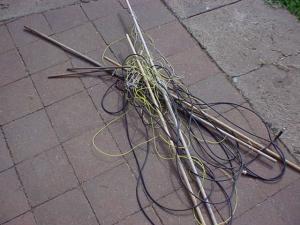
My first attempt at setting up a phased array antenna at Mick's place
involved some thin pieces of dowel, each held in place by some string
and three tent pegs. The local bovine really liked this antenna design
and, in the end, my first antenna ended up in the mess you see in the
photo to the left. The second attempt is a lot more robust, at the cost
of involving lots of steel star pickets, which may have an impact on
the antenna beam pattern, but, hey, at least the things stay upright!
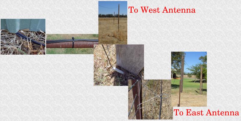
The first objective was to keep the antenna feedlines from being eaten,
and also to try and keep them inconspicuous. This took the combined
brain-power of Chris, Mick and I. The feedlines slip out of the shed,
where the radios and computer live, and then run along the fence
together for about 30m. At that point, the feed for the Western antenna
goes up a custom made "sky hook" (a plank of wood screwed to a star
picket, with a groove cut in the top to hold the coax). It wanders
across about 20m of grassy field using three sky hooks.
The feedline for the Eastern antenna goes underground, in some conduit,
for about 1m, where the gate is, and then runs along the fence, using
simple wire standoff loops, for about 15m. At this point the coax runs
up a skyhook, across to another skyhook, and then drops down to the
East antenna. The whole layout is pictured in the composite below.
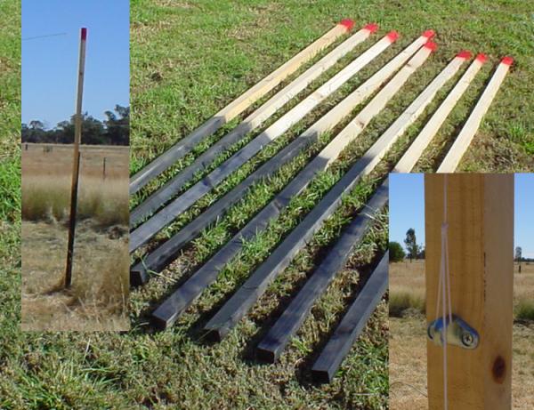
The dipole antennas are help up by some 2.7m tall bits of 55x35mm wood
that I got for $20 from a local store because they were slightly
warped. I painted them up real snazzy so they would work better. I
drilled a hole through the top of each length of wood to feed a piece
of string through and affixed a lashing hook, used to adjust the amount
of tension on the dipole. Each of the pieces of wood is kept vertical
by virtue of being thrice screwed to a star picked, bashed into the
ground at the right location. Rose, Chris and Dazza helped to find the
right location and do the bashing.
The dipoles themselves are made of thick copper wire, purchased as
"Earth wire" at a local store. The centre insulators are thin pieces of
wood with three cable fasteners to take the tension of the solder
joins. In fact, we couldn't get the braid of the RG6 to solder, so I
had to attach it to the antenna using a piece of tag block. I soldered
a tiny loop of wire onto the other end of the dipoles so that I could
tie the tensioning string to them.

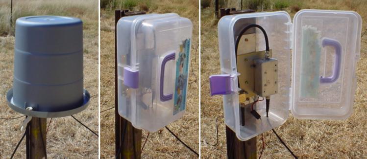
The drop lines from each pair of dipoles go into a "weather proof" box
(consisting of a plastic tackle box screwed to a bit of wood on a star
picket, with a bucket over it). They are fed into a Radioshack 75ohm
splitter/combiner, that Dusty sent to me. The combiner output is fed
into a box housing a 7-pole 30MHz low pass eliptic filter and a MAR-08
amplifier with 31dB of gain and a 4dB noise figure. Daron Brooke helped
me to test these units. At the moment they are battery powered, more
photos coming soon. The output of the amplifiers are fed into the RG58
feedlines described above.
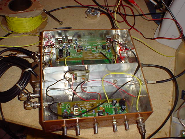
On the other end of the feedlines are the radios themselves. These are
Ten-Tec 1056 radio kits with some modifications made to them. You can
gather why YASI is also called the Biscuit Tin Telescope, notably by
Tim.
Chris and I surveyed the baseline using a measuring tape, a handhelp
GPS and a compass. I think we did pretty well at getting 45m East-West,
in the end.
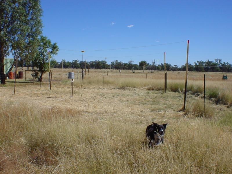
A complete antenna is shown in the photo below (along with Cassie). In
the background, barely visible, is the second antenna 45m to the West.
If you look right near the middle of the photo you can see the silver
bucket of the other antenna. This Eastern antenna has an extra four
star pickets around the perimeter, these will be used to install a
bovine proof fence.
