This appendix describes in detail all the fields and buttons available in the CABB web scheduler, and how to use them.
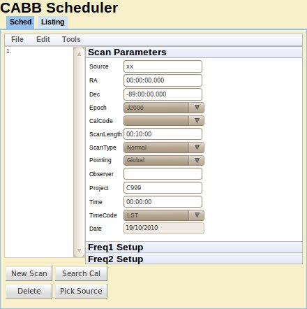
SourceThe name of the source. If the name of a calibrator in the ATCA calibrator database is entered into this field, the scheduler will automatically fill the
RA,Dec,EpochandCalCodefields. The information in this field will be used by the correlator as the name of the source in the output FITS files. If observing a mosaic, this field should be set to the name of the mosaic file describing the mosaic pointings, without the.mosextension.RA & DecThese fields define where on the sky you want the array to point, ie. the phase centre. You must specify
RAin hours, minutes and seconds separated by colons (:), and you must specifyDecin degrees, minutes and seconds separated by colons (:). TheRAandDecwill be in the system defined by theEpochfield, thus they can also be used to represent azimuth and elevation angles, and Galactic latitude and longitude.EpochThis defines the coordinate system used for the
RAandDecfields. Four epochs are recognised:J2000 (default)
B1950
Az/El (horizon coordinates)
Galactic
CalCodeA flag used to specify if a certain source is meant as a calibrator. It should either be “
C” for a calibrator, or blank for a non-calibrator. For baseline solutions, theCalCodeis set to “B”, a feature that should not be used by normal observers. When a calibrator is selected from the “Search Cal” screens, or matched from input to theSourcefield, this code will automatically be set to “C”. TheCalCodefield is reset to blank after a new scan is added to avoid inadvertantly calling a target source scan a calibrator scan.The assistance program makes use of the
CalCodefield to determine the level of on-line checking that is done. If a calibrator scan is indicated, the checks (for stable amplitude, small delays, closure phase, etc.) are more stringent. If a calibrator scan is not labelled with “CalCode=C” then these checks will not be performed. On the other hand, most target sources have structure and insufficient flux, so assistance would sound alarms continuously if a source like that was marked as a calibrator scan.ScanLengthThis indicates the length of time to spend on the current scan. It is specified in time format and should be specified as
HH:MM:SS, whereHH,MMandSSare the number of hours, minutes and seconds to spend on the source respectively. Unless theScanTypeis set toDwell, the scan time includes the time to drive to the source. The scan must be at least four integration cycles long.For many types of scan, this field is essentially meaningless, although it must always be set to four integration cycles or longer. For
Point,PaddleandClosefilescans, the scan will take as long as it needs to, and the setting of theScanLengthfield is unimportant.ScanTypeThis field specifies special scan characteristics:
Normal: the scan will go for the length of time specified byScanLength, inclusive of all slewing/setup time to get on source. For example, ifScanLengthis set to 10 minutes, then the scan will go for 10 minutes, even it takes 2 minutes to slew to source; in this case, only 8 minutes of data will be collected on-source.Dwell: the scan will go for the length of time specified byScanLength, in addition to any slewing/setup time incurred while moving to the source. For example, ifScanLengthis set to 10 minutes, and the telescope takes 2 minutes to slew to source, then this scan will go for 12 minutes, and 10 minutes of data will be collected on-source.Mosaic: this must be selected to indicate that this scan is a mosaic scan, and that theSourcefield should be interpreted as the name of a mosaic file.Point: indicates that this scan should be executed as a pointing pattern, which can be used to determine offsets for each antenna. This may be used for global pointing solutions as performed by local staff, or for reference pointing during observations.Paddle: indicates that the paddle should be inserted during 3mm observations; this scan type will have no effect during observations at other bands.Closefile: placing a scan with this scan type in a schedule causes the correlator to close the current file when it reaches this scan. No other scan parameters are interpreted when this scan type is specified. This is useful for keeping file sizes small, or for separating files based on the number of times the schedule has looped. The correlator will automatically start a new file when the next scan begins.OTFMos: this must be selected to indicate that this scan is an on-the-fly mosaic scan, and that theSourcefield should be interpreted as the name of a mosaic file.
PointingThis field specifies the pointing mode of the antenna during the scan. Options are:
Global: the default pointing mode. It uses the global, all-sky pointing model determined at each reconfiguration.Offset: uses the offsets from the latest pointing solution (which should be determined on a nearby calibrator) to improve the pointing locally (near the calibrator) and for a limited time (offsets are time variable). For experiments that track only a single source and a nearby calibrator, this is the safest pointing mode to use.Offpnt: instructs caobs to find the best pointing solution for this scan by looking through all pointing solutions from the previous two hours, and selecting the one closest in az/el position and frequency. If no suitable pointing solution is found, it reverts to the global pointing model, which may cause serious problems, especially at 3mm wavelengths. This mode should be preferred overOffsetpointing if many widely-separated sources are being observed together.Refpnt: determine new local pointing offsets by executing a pointing pattern on a calibrator. Using thisPointingmode causes the telescope to be put into global pointing mode before the new offsets are determined. This option only makes sense when combined with aScanTypeofPoint, and this should only be done while observing a calibrator.Setting
PointingtoRefpntwill make the scheduler automatically set theScanTypetoPoint.Update: determine new local pointing offsets by executing a pointing pattern on a calibrator. Using thisPointingmode causes the newly determined offsets to be added to the previously determined pointing solution. This option only makes sense when combined with aScanTypeofPoint, and this should only be done while observing a calibrator.Setting
PointingtoUpdatewill make the scheduler automatically set theScanTypetoPoint.
If you choose to have a
ScanTypeofPointand aPointingthat is notUpdate, the scheduler will popup a query box asking if you are sure this is what you want. For normal observations, you should always havePointing=UpdateforScanType=Pointso that the pointing offsets determined during the pointing scan will be used for all subsequentOffsetandOffpntscans. There may be other cases where the observer does not want the pointing to be automatically updated (such as during an array reconfiguration), which is why this option is not strictly forbidden.ObserverThis is an ASCII string up to 12 characters long that is used to identify who made the observations. It is not critical to any on-line system and is merely a label for reference.
ProjectThis is the project identification number (
nnn) allocated to observing projects, and should be specified here asCnnn. TheProjectfield value is used by cacor to name the extension of the output RPFITS files. It is important that it is set correctly as it is used for record keeping and by the ATNF Online Archive. The defaultC999code is used for system testing and test files; such files will not be considered as valuable when it comes to deleting data.The scheduler will complain if you enter a schedule file that doesn't look like
Cnnn,CXnnnorVnnna(the latter being a VLBI project code). You can choose to ignore the warning, and the scheduler will save the schedule, but it is strongly advised that you do not use a project code that does not fit the above pattern.TimeThe value of this field can only be set for source 1 in the schedule, and is used as the start time of the schedule. If
TimeCodeis set toLST, then this value is only used for calculation of slew times and elevations by the scheduler's listing tab, and will be ignored by caobs. IfTimeCodeis set toUTChowever, caobs will treat the schedule as an absolute time schedule, so each scan will only be executed between the time specified here (on the date specified in theDatefield) and the time plus the value inScanLength. This will usually only be useful when coordinating the activities of the ATCA with other telescopes (such as for VLBI).TimeCodeThe selection made here sets the type of time desired for the
Timefield above. It can be either local sidereal time (LST) or coordinated universal time (UTC). This field can only set for source 1 in the schedule. See the description of theTimefield for the consequences of setting this field to UTC.DateThe observing date can be set here to allow the scheduler to correctly determine the source positions and drive times. Of course, the date does not matter when setting LST, but is of vital importance when the
TimeCodeis set to UTC.This field is also used when the scheduler calculates the apparent frequency of a spectral line, which will be affected by the velocity of the Earth on the date specified here.
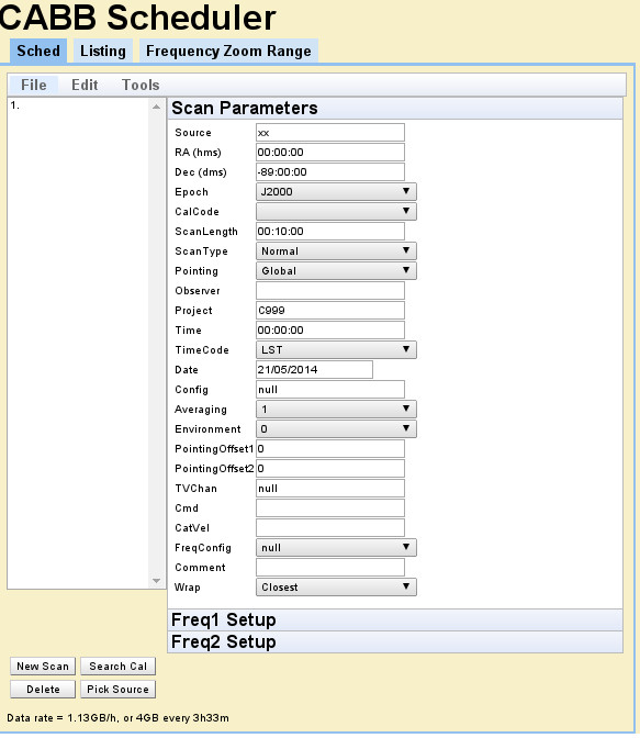
ConfigThe value of this field may (eventually) be used to configure the correlator. Currently, there are only a few easily-usable correlator configurations, and this field should be left blank, or given the default value of
null.AveragingThis parameter specifies the number of cycles to average together when writing the data out to an RPFITS file on disk. Averaging will restart on source and frequency changes. We do not recommend that this field is set to values larger than
1.EnvironmentSetting this field requests caobs to record the attenuator and sampler settings assocated with each different field value, and recall those settings whenever a scan is encountered with the same value. Each frequency setting (modulo 1 MHz) allows for up to 128 such values. Valid
Environmentvalues are from 0 to 127.PointingOffset1 & PointingOffset2Use these fields and the
OffpntPointingtype to make the telescope point away from the specified RA & Dec.PointingOffset1is the offset in seconds to move in RA, andPointingOffset2is the offset in arcseconds to move in Dec. Remember that the phase centre of the observation will always be at the position given in theRAandDecfields. Therefore if you wish to use these offset pointing fields to avoid a potential DC offset issue, you must put an offset position inRA,Decand then usePointingOffset1andPointingOffset2to shift the pointing centre to be on source again.TVChanWhen switching between different observing frequencies, the usable range of correlator channels will also change, due to RFI or bandpass shape. The correlator uses only a certain subset of channels – called the TV channels – to determine system temperatures, and if the TV channels are not kept constant for each individual frequency config then you may encounter amplitude problems later in the reduction process. The TV channels setting also affects what is displayed by vis. This parameter allows you to set the TV channels on a per scan basis, which makes frequency switching a far more automated process. This parameter should be either
nullto allow the current TV channel setting to be left as-is, or a set of four numbers, separated by commas, indicating (in order) the first and last TV channel for IF 1, and the first and last TV channel for IF 2.During normal frequency-switching observations, cacor will itself remember the TV channels on a per-frequency basis, and restore them as the frequencies change. If everything works as expected, this scheduler field is not required. This field is here in case you don't want to rely upon cacor's memory.
CmdThis field can be used to instruct caobs to issue one or more commands each time it starts this scan. Multiple commands may be specified, separated by semi-colons, although this field has an 80 character limit. Each command must be a recognised caobs command. For example, the tied-array configuration could be changed by specifying
corr catie ant 123456 123456; corr catie gain 0.2 0.2The first command listed in this field will be executed as soon as the scan is started, and each subsequent command will be executed as soon as the previous has been processed. To allow more flexibility in the timing of the commands listed in this field, there is a special command
WAIT n. This command (which cannot be used in manual caobs operation), waits fornintegrations after the start of the scan. After this condition has been met, the commands after theWAITcommand are executed. For example, to calibrate the phases after 5 cycles (to allow for data collection), specifywait 5; corr pcalThere are important caveats on the
WAITcommand. It does not guarantee on-source cycles will be waited: if the commandwait 5is specified, but it takes 5 or more cycles before the telescope gets on-source, the subsequent command will likely be executed before valid data is collected. To guard against this, consider putting a dummy scan before the scan with the command specification. The dummy scan should have a small (one or two cycles) amount of dwell time so that caobs will wait until the telescope is on-source before proceeding to the next scheduled scan.The
WAITcommand is not a progression command either. Take for example the following command:wait 5; corr dcal; wait 4; corr pcalThis command will fail to do what you might naively expect, because after thedcalcommand is issued, it will immediately issue thepcalcommand. This is because thewait 4command will immediately exit, as caobs has already waited for the fifth cycle to start, so it will no longer wait for the fourth cycle. Instead, this command should be:wait 5; corr dcal; wait 9; corr pcalCatVelThe
CatVelfield can be set manually, or via the scheduler's "Pick Source" function. This allows for rapid and reliable frequency calculation with the scheduler's velocity calculator, as the information in this field is automatically propagated into the calculator. This field should be set as three values, separated by spaces as follows:velocity velframe velconv
Here,
velocityis the velocity of the source in km/s (recession is positive),velframeis the frame in which the velocity is measured (one ofLSRorBary), andvelconvis the velocity convention (one ofRadio,OpticalorZ).This field must be set if you want to use the scheduler's zoom range checker.
FreqConfigThe
FreqConfigfield is used to create a number of frequency and zoom settings that can be shared between scans. Setting the continuum frequencies and specifying up to 16 zooms in each IF can be tedious and error prone if it has to be repeated for many scans. TheFreqConfigfield lets you select one or more scans asMasterscans and then assign other scans to beSlavescans. EachSlavescan inherits the exact frequency and zoom settings of the correspondingMasterscan. Using this you can ensure source and calibrator are observed with the same settings, even after recalculating velocities and frequencies for a different date. The default setting ofnullleaves the settings independent of other scans.CommentThis field can be used to leave comments for yourself in the schedule. It is it not used on-line, nor is this entry available outside the scheduler.
WrapThe ATCA can be in one of two “wraps”, and the azimuth ranges observable in each wrap are different, although they overlap. This field can be used if you want to control which wrap to use for your observations. It can take one of three values:
Closest,SouthorNorth. See Section 2.3.10 for a description of the wraps.
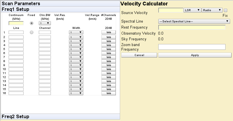
Continuum (MHz)Enter the central frequency (in MHz) of the 2048 MHz continuum IF here. There is one of these fields in each of the
Freq1andFreq2tabs, one for each available CABB continuum IF. If after entering a frequency in this box, the box text turns red on a yellow background, it means the frequency is invalid when considered with the frequency specified in the other IF. Putting the mouse over the frequency box will give you some information on how you might rectify this situation.Chn. BW (MHz)Select how wide (in MHz) each continuum channel will be for each IF. The channel width will also set the minimum bandwidth of each zoom band derived from this IF. There is one of these fields in each of the
Freq1andFreq2tabs, one for each available CABB continuum IF.LineEnter a frequency (in MHz) that will appear within the zoom band. The scheduler will then calculate the continuum (or offset continuum) channel that would have this specified frequency closest to its centre. This frequency must be within 1024 MHz of the frequency specified in the
Continuum (MHz)field. A maximum of 16 such bands can be specified in the scheduler for each IF when using a channel bandwidth of 1 MHz or 64 MHz.ChannelEnter the wideband channel number to use for the zoom band. This will then restrict the frequencies available in the zoom band.
WidthThis is the number of continuum channels to use for this zoom band. Note that a maximum of 16 continuum channels can be used in each IF. Some of the
Widthboxes will be disabled if more than 1 continuum channel is assigned to any particular zoom band.FixedUse this to select whether to keep the continuum frequency fixed or keep the frequency of the first zoom fixed when you change the
Channel,Widthor velocity.VeloThis button brings up the velocity calculator that lets you specify the source velocity and rest frequency to calculate the sky frequency of the spectral line. The sky frequency is rounded to the nearest possible frequency setting of the telescope and entered in the schedule when you press the
Applybutton.FixThis tick box appears on the velocity calculator. When ticked, the same velocity setting will be used for all zooms on both frequencies. Use this to avoid having to enter the same information many times when the source has many spectral lines with more or less the same velocity.